T-P23 low voltage fault locator for finding permanent and intermittent faults on live cables
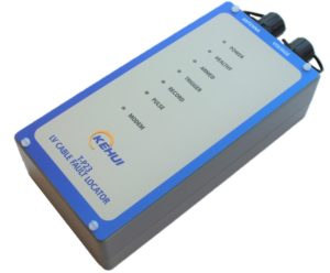
The Kehui T-P23 has been designed for locating all types of low voltage cable fault, but especially the difficult and troublesome transient and intermittent fault. It is especially suitable for branched cables. This can be useful to detect the direction of current flow. Watch the video
The device has three modes of operation; Time Domain Reflectometry (TDR) where a single unit is used, Travelling Wave (TRS) using simultaneous testing from two units and Voltage Gradient using records from two or more units. The unit can be connected to a suspect cable and can then be controlled locally from a portable PC through its internal Bluetooth transceiver, or remotely over the Internet using its integral GSM/GPRS modem. The resulting signals can be examined in the T-P2X system software to identify the position of the fault.
LV cable systems are susceptible to transient fault conditions. Damage to an underground cable may only become apparent when moisture causes the fault to ignite resulting in flickering lighting or the rupturing of the associated fuse. The heat of the fault can cause the moisture to evaporate apparently returning the system to normal and allowing the fuse to be successfully replaced. However, the underlying problem remains.
The situation is further complicated by the construction of LV systems in many parts of the world, which do not allow the isolation of the suspect part of the cable. This prevents it from being treated by an HV surge generator to make the fault permanent. The situation is further complicated as the cables have many branches with direct connections to customers’ premises.
One solution is to monitor the cables with a T-P unit acting as a Time Domain Reflectometry (TDR) unit regularly injecting TDR signals into the cable. The data can then be stored on a cyclic basis, until such time as a fault occurs. The fault will trigger the device and saves the data in such a way that the location can be determined through the comparison of pre and post fault data.
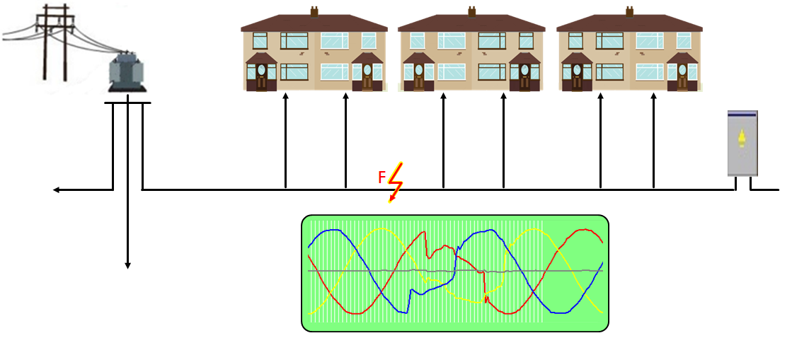
The device can be situated in a convenient point of the network, such as the substation, fuse pillar or link box but it must be at an “open end”. This means that it must be positioned so the TDR pulse can only travel in one direction towards the suspected fault, as other paths will result in reflections that confuse the results. Clearly this requires there to be an alternative supply to keep the consumers on line. As the speed of propagation of the pulse is known, its timing can be used to calculate the distance to fault.
Blocking Coil
If there is space available in the installation the unit can be connected in series with a blocking coil, which is located between the device and the busbar.
The coil will appear as an ordinary piece of cable to power frequency signals (50/60Hz) but its inductance will present a high impedance to the high frequency TDR pulses. This will prevent the pulses passing in to the busbar and makes the connection a virtual open end.
TRS MODE
To avoid the complication of the open end, an alternative configuration is possible using two units, which can be located at suitable parts of the system. This makes use of the phenomenon of travelling waves which are produced by the fault and are detected by the units at either end of the monitored section. An internal algorithm synchronises the units without the need for external equipment. Each unit can measure the time taken for the wave to reach it and the speed of the wave along the cable is known, hence the distance to the fault can be calculated.
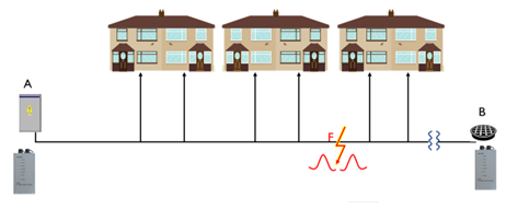
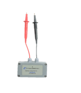
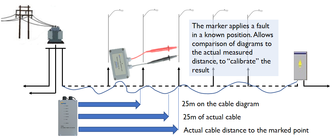
To compensate for this, a marker unit can be used to calibrate the measurement. The marker is used at an accessible point on the cable, such as a lamp-post. The unit can then be touched on to the cable terminals, producing a signal which will trigger the T-P23 without affecting the supply. The T-P23 will then indicate the distance to fault, which can be compared to the actual distance between the substation and the lamp-post (or other access point). This will help the user to identify the true fault position, based on the T-P23 reading.
Features:
- Remotely controllable TDR and Disturbance Recorder designed specifically for low voltage power cable fault location
- Locates permanent, intermittent and transitory faults
- Safe connection to energised cables via heavy duty fused test leads
- Local interrogation through a Bluetooth connection to a PC or Android device
- Internal GSM/GPRS modem allows control and interrogation from anywhere in the world
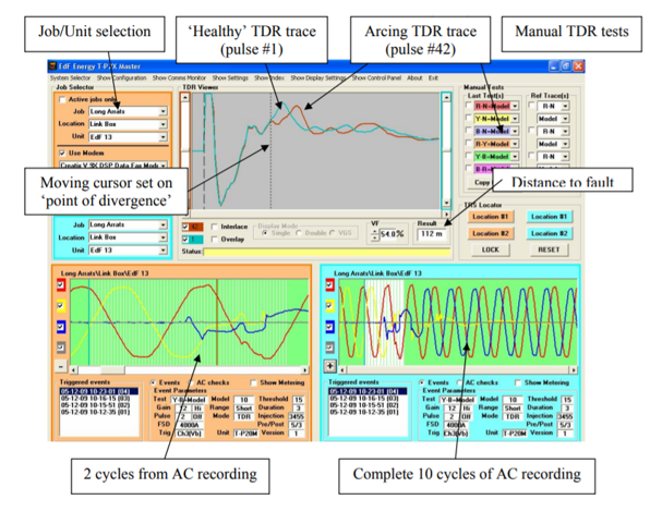
- Storage of the last 20 events with 64 TDR traces (30 pre-fault and 34 post-fault) plus 10 cycles of AC voltage waveforms
- Triggered from voltage distortion
- Used in conjunction with additional devices it can provide a 3-phase voltage gradient fault location system. Two, or more, units can be configured to operate as a quasi-synchronous Travelling Wave Fault Location System
Full Description
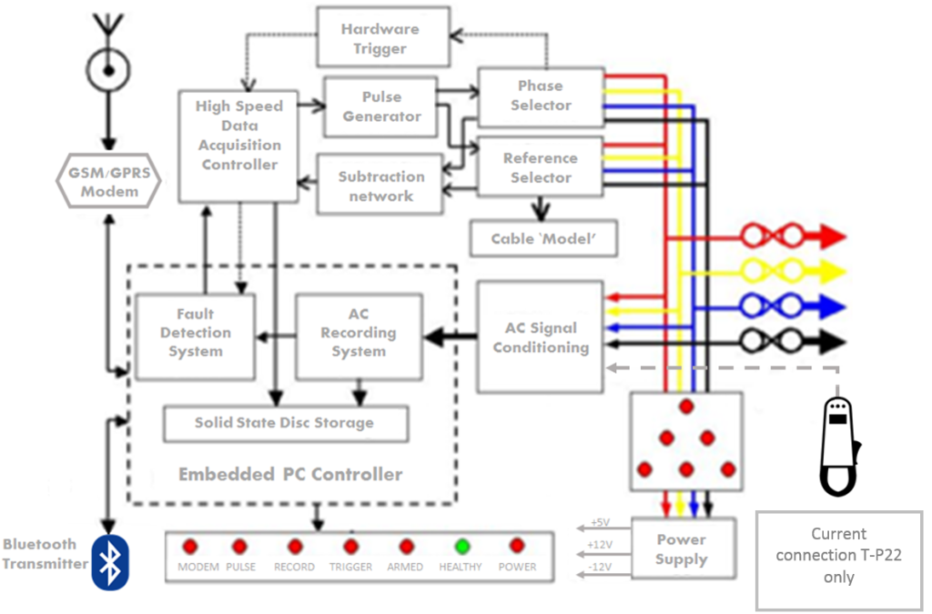
The T-P23 has been designed to locate all types of low voltage cable faults, but especially difficult and troublesome intermittent faults. It can be controlled locally from a portable PC or remotely over a telephone channel (either landline or GSM). The unit is connected simultaneously to all 3 phases of an LV cable to allow the local or remote operator to perform TDR testing on any combination of phases. Power for the device is taken through the 3-phase test lead so it requires at least 1 phase to be energised. It includes a three- channel transient recorder which is used to acquire information about the nature and behaviour of intermittent faults. The signals acquired by the transient recorder are also used to detect “trigger” conditions for the TDR system based on current or voltage distortion.
Voltage recordings from several of devices can be used for fault location by voltage gradient. By allowing control from a remote location, the units can be connected to a faulty cable by field staff who are not necessarily familiar with the analysis of TDR waveforms. The expertise in adjustment and interpretation being provided by a centrally located specialist. This becomes particularly beneficial when the equipment has to be left on-site awaiting the (re)-occurrence of an intermittent fault.
Related downloads:
- Software & Instructions
T-P2X Master software
Instructions for installing T-P2X Master
SIM card replacement - Documentation
T-P23 User Manual
T-P23 Datasheet
T-P23 Brochure