T-NM1 LV Cable Network Model
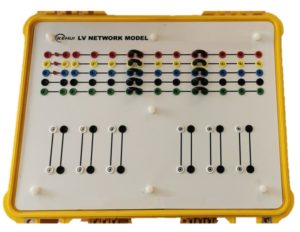
The Kehui low voltage (LV) cable network model simulates a cable system for training and development applications. It is built using actual LV cable, which provides a more realistic representation of the network than can be provided by component-based models or software simulations. The flexible design allows branches to be added to the network at different positions and for various faults to be simulated.
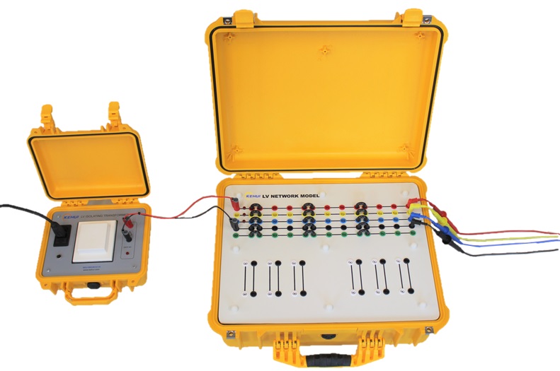
Although the device can be used in a variety of ways, its principal application is to facilitate the use of fault location equipment for training and testing purposes. The network can be used unpowered, to demonstrate the use of fault locators using time domain reflectometry (TDR) technology, or it can be energised using the Kehui T-NMS1 power supply to allow the operation of live network monitoring devices, such as the Kehui T-P23.
Features
- Accurate 3 phase representation of LV network of up to 200m in length
- Neutral and earth paths included
- Can be energised using an isolating transformer
- Simulation of permanent and transient phase and earth faults
- Flexible arrangement of line length and branch locations
- Standard 4mm shielded plug connections
Specifications
The LV cable network model consists of 4 cable groups of shielded 4-core cable, of differing lengths, divided in to 10 sections as indicated on the table below:
Length of each cable group and sub-section
| Group | 1 | 2 | 3 | 4 | ||||||
| Length (m) | 10 | 55 | 75 | 60 | ||||||
| Section | 1 | 2 | 3 | 4 | 5 | 6 | 7 | 8 | 9 | 10 |
| Length (m) | 10 | 25 | 15 | 15 | 35 | 30 | 10 | 15 | 15 | 30 |
The groups can be joined together using the U-shaped jumper leads provided. These can be removed to either shorten the cable or introduce an open circuit on chosen phases. Permanent faults can be introduced by connecting the faulted phases together or to earth, whilst intermittent faults can be simulated using the push-button accessory T-NMA1.
To simulate an LV branched network, there are six, 2-core single-phase cables (each 10 meters in length) which can be used as single-phase branches or by combining three together, as one or two, 3-phase branches.
Network simulator energised by the T-NMS1 isolating transformer.
Accessories
T-NMS1: Isolating power supply
T-MU1: Marker unit (for live working)
T-MU240: Marker unit for live working