SRM/SRD – Introduction
The technology behind the switched reluctance motor (SRM) has been in existence since the mid-nineteenth century. These early examples never reached their potential because they were difficult to control, noisy and unreliable. However, with recent developments in electronic switching, using insulated-gate bipolar transistor (IGBT) technology, the SRM have become an excellent solution for a wide variety of different applications. The latest designs of SRM allow users to take advantage of the higher efficiency, low starting currents and robust construction that characterises this type of motor.
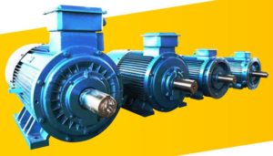
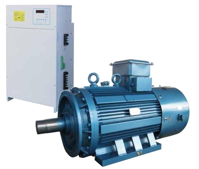
Since 2000, Kehui has been working on the development of SRD motor systems and has regularly introduced new generations of drives, culminating in the KSM20 controller series, with a maximum power of 500kW (670Hp). Coupled with the HS1 SR motor designed for high impact and high vibration applications, the Kehui switched reluctance motor systems are true world leaders with production of approximately 2,000 motor sets per year.
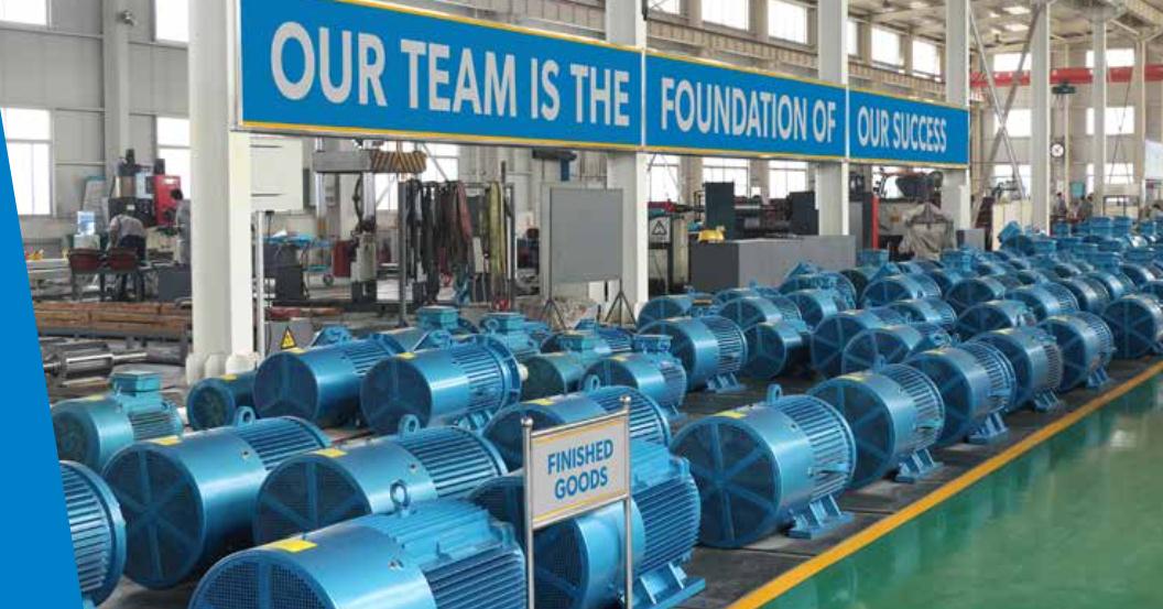
The company’s capabilities are emphasised by its investment in a state-of-the-art SRD test facility to ensure that its commitment to quality is maintained.
The Switched Reluctance Drive (SRD), a combination of the motor and its electronic control system, creates a low cost, reliable, highly effcient, and flexible electric drive system. Its ability to use potential energy stored in one coil to energise the next, takes this technology to a whole new level of effciency and performance. An SRM does not
have magnetic “slip”, so there is virtually no heating of the armature (which is a weakness of standard induction motors). The losses that do occur are in the magnetic coils connected to the stator, where heat is more readily dissipated. As SRDs do not have bi-directional, three-phase, high frequency switching, they do not have the eddy and bearing current issues commonly associated with squirrel cage (induction) motors.
The technologies that make up SRDs are well established and use commonly available parts and materials; the difference is how they are combined and applied. Because of this, SRDs are not accompanied by a “leap in technology” risk that affects many new solutions. Specifying, purchasing, installing, commissioning, maintaining and operating Kehui SRDs is little different to a conventional Variable Frequency drive (VFD) system. However, there will be a substantial reduction in costs for all of these activities.
Benefits of SRD
- Low starting current
- High starting torque
- Robustness
- Simplicity and reliability
- High Power
- Frequent rotational direction changes
- No need for magnets or rare earth metals
- High overload capacity
- Efficiency
- Frequent stopping and starting (up to 1000 times per hour)
- Excellent dynamic response
- The absence of bearing currents prevents potential damage[…]
Features and benefits
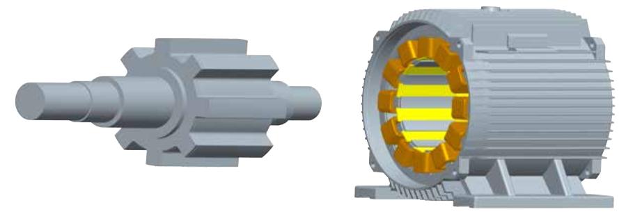
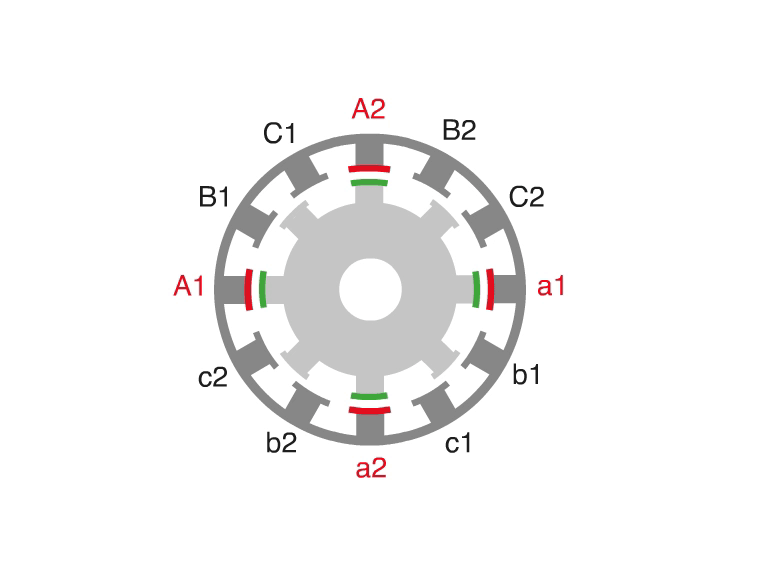
The rotor of SRM is made of laminated silicon steel sheets with no windings or permanent magnetic material. This makes it extremely strong, such that it can withstand frequent shocks received in applications such as press machines.
Frequent Stopping and Starting with High Starting Torque and Low Current
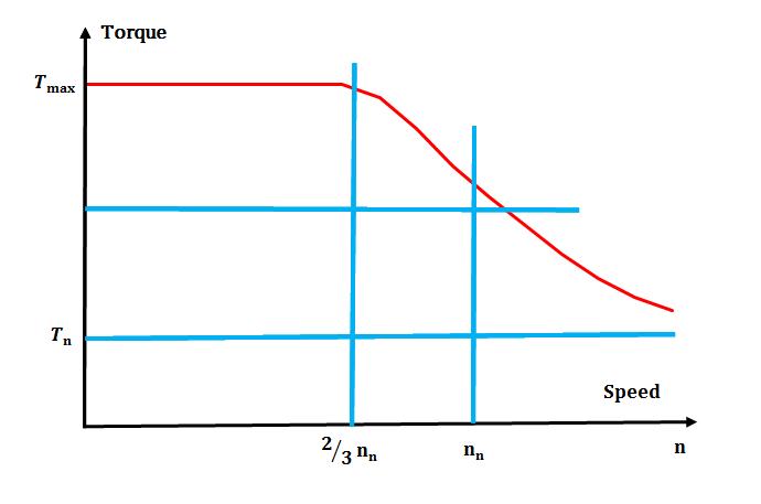
The starting torque of the motor is greater than 3 times the rated torque. Yet when the starting torque reaches 150% of the rated torque, the starting current is only 30% of the rated current. This is applicable for multiple starts and reversals up to 1000 times per hour.
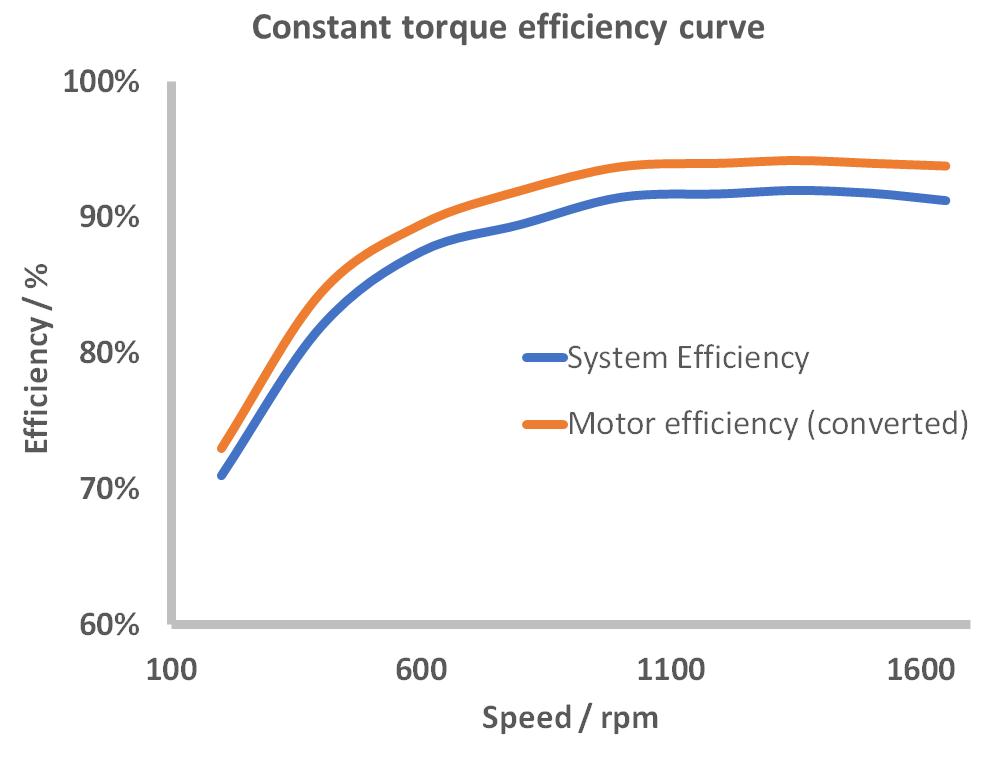
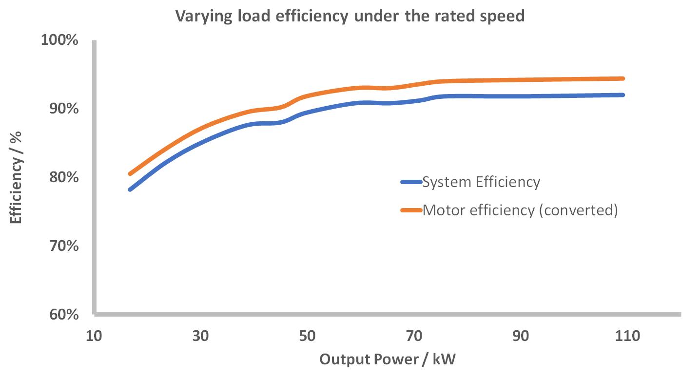
Efficiency
The SRM drive system can reach up to (IE4) “Super Premium Efficiency” limits (in accordance with IEC/EN 60034-30-1:2014). This efficiency is especially evident at low speeds and light loads and is maintained across a wide speed range.
How does it work?
The switched reluctance drive (SRD) system consists of an SRM and its associated control system.
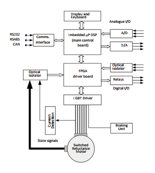
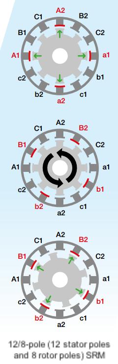
The electrical power is delivered to the SRM windings positioned around the stator, which create a magnetic field. The magnetic reluctance of the rotor results in its poles aligning with an energised stator winding. By using an electronic switching circuit to sequentially energise the windings around the stator, the rotor isattracted to the magnetic field on each stator pole in turn and hence, rotates until it is aligned. If the relative positions of the stator and the rotor in the diagram are taken as the starting position energising the B phase winding will result in the rotor rotating anti-clockwise against the excitation sequence. The direction of rotation of the motor is independent of the direction of the current in the phase winding and the current of the stator winding of the switched reluctance machine is uni-directional.
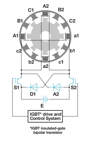
The KSC20 series controller controls the switching of the magnetising current consecutively from one stator winding to the next, causing the rotor to rotate. The switching is carried out electronically. The controller also facilitates changes to the motor’s speed, torque, braking and direction.
Bearing current
- Bearing current with variable frequency drives
With the application of variable frequency (VF) speed control technology, damage due to bearing current has become increasingly problematic. Due to the presence of high frequencies, voltage can be generated on the motor shaft due to coupling through the internal capacitance of the motor. This can result in a common mode current flowing through the motor bearing.
- The impact of bearing current
When the shaft voltage exceeds the withstand value of the bearing grease insulation, the bearing will produce a destructive shaft current. This may result in a melted pit in the bearing race, which eventually creates a groove. This will increase the friction of the bearing, and shorten its life.
- Benefit of SRD
SRD Motors do not generate shaft current as their windings are symmetrically distributed. The internal magnetic field of the iron core is also symmetrical, and no voltage drop occurs at either end of the motor shaft. The motor windings are independent and so the mutual inductance is small. Additionally, there is no neutral point so there is no state of voltage imbalance. As a result bearing currents are not a problem for motors using switched reluctance technology.